Section 2: Electricity
(a) Units
2.1 use the following units: ampere (A), coulomb (C), joule (J), ohm (W), second (s), volt (V), watt (W).
- Unit of current: ampere (A)
- Unit of charge: coulomb (C)
- Unit of energy: Joule (J)
- Unit of resistance: ohm (Ω)
- Unit of time: second (s)
- Unit of voltage or potential difference: volt (V)
- Unit of Power: watt (W)
(b) Mains electricity
2.2 understand and identify the hazards of electricity including frayed cables, long cables, damaged plugs, water around sockets, and pushing metal objects into sockets
Mains electricity: The source of electricity in our houses is called mains electricity.
Electricity meter: The meter that measures the electrical energy we consume in our house is called electricity meter.
Fuse box(or Consumer unit): The box that contains all fuse and circuit breakers in a circuit is called fuse box.
Ring main circuit: Wires that leave the fuse box are hidden in the walls or floors around each room. These wires are connected to form ring main circuits. Individual equipments are connected to these circuits using plugs. It consists of three wires: live wire, neutral wire and earth wire.
Live wire: The wire that contains the electricity all the time is called live wire.
Neutral wire: The wire that usually doesn’t contain the electricity but when it is connected with the live wire then it also become live. The neutral wire completes the circuit.
Earth wire: The earth wire usually has no current flowing through it. It is there to protect user if an appliance develops a fault.
Electricity is very useful, but it can be dangerous if it is not used safely. The following hazards that increase the chances of severe and possibly fatal electric shocks are:
- frayed cables, any damaged insulation can expose ‘live’ wires.
- Long cables, as they are more likely to get damaged or trip people up.
- Damage to plugs or any insulating casing on any mains operated devices.
- Water around electric sockets or mains operated devices.
- Pushing metal objects into the mains sockets – usually only a problem with very young children, solved by using socket covers.
2.3 understand the uses of insulation, double insulation, earthing, fuses and circuit breakers in a range of domestic appliances
Insulation: Some appliances are cased with insulators like plastic rather than metal to prevent user from receiving shock. This casing is called insulation.
Double Insulation:Some appliances are double insulated; as well as all their wiring being insulated the outer casing of the appliances is also made of an insulating material. This means there is no chance of an electric shock from the casing – double insulation is often used with electric kettles and power tools like electric drills.
Earthing: Many appliances have a metal casing. This should be connected to earth wire so that if the live wire becomes frayed or breaks and comes into contact with the casing, the current will pass through the earth wire rather than the user. The current in the earth wire is always large enough to blow the fuse and turning off the circuit. So the user is safe from electric shock.
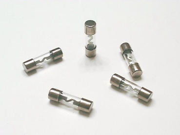
Fuses: Fuse is a safety device usually in the form of a cylinder or cartridge which contains a thing piece of wire made from a metal that has low melting point. If too large a current flows in the circuit the fuse wire becomes very hot and blows, shutting the circuit off. This prevents you getting a shock and reduces the possibility of an electrical fire. One the fault in the current is corrected, it should be replaced again.
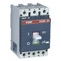
Circuit Breakers or Trip switches: Circuit Breaker is similar to fuses. If too large a current flows in a current a switch opens making the circuit incomplete. Once the fault in the circuit is corrected, the switch is reset, usually by pressing a reset button.
 |  |
|---|---|
| inside | outside |
How does a circuit breaker work?
When high current flows, the electromagnet in it gains its magnetism and attract the iron catch towards it. This separated the contact and the circuit discloses.
Switches: Switches in main circuit should always be included in the live wire so that when the switch is open, no electrical energy can reach an appliance. If the switch is included in the neutral wire, electrical energy can still enter an appliance, and could possibly cause an electric shock.

2.4 understand that a current in a resistor results in the electrical transfer of energy and an increase in temperature, and how this can be used in a variety of domestic contexts
Normal wiring in the house are said to have low resistance and the current pass through them easily. Heating elements like nichrome wire have high resistance. When current flows through them current cannot pass, and the energy is transferred to heat energy and the element heats up.It is also used in the lights – normal light bulbs have a very thin filament which gets so hot when current passes through it that it glows white. We use the heating effect of current in electric kettle, iron, filament lamps, fan heaters, hair dryers etc.
2.5 know and use the relationship: power = current × voltage, P = I × V and apply the relationship to the selection of appropriate fuses
Power is amount that represents how much voltage or energy is converted every second. It is calculated using this equation:
Power, P (in watts) = current, I (in amps) x voltage, V (in volts)
P = I x V
Fuses in plugs are made in standard ratings. The most common are 3A, 5A and 13A. The fuse should be rated at a slightly higher current than the device needs:
- if the device works at 3A, use a 5A fuse
- if the device works at 10A, use a 13A fuse
2.6 use the relationship between energy transferred, current, voltage and time:
Energy transferred = current × voltage × time
E = I × V × t
The power of an appliance (P) tells you how much energy it converts each second. This means that the total energy (E) converted by an appliances is equal to its power multiplied by the length of time the appliance is being used.
Total energy, E (in joules) = power, P (in watts) x time, t (in seconds)
E = P x t
Since, P = I x V
E = I x V x t
2.7 understand the difference between mains electricity being alternating current (a.c.) and direct current (d.c.) being supplied by a cell or battery.
Alternating current:

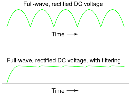
If the current constantly changes direction, it is called alternating current, or a.c.. Mains electricity is an a.c. supply, with the UK mains supply being about 230V. It has a frequency of 50Hz (50 hertz), which means it changes direction, and back again, 50 times a second. The diagram shows an oscilloscope screen displaying the signal from an a.c. supply. Alternating current is useful in electricity generator and transformers.

Direct current:

If the current flows in only one direction it is called direct current, or d.c. Batteries and cells supply d.c. electricity, with a typical battery supplying maybe 1.5V. The diagram shows an oscilloscope screen displaying the signal from a d.c. supply.
Alternating current can be converted to direct current by using a rectifier. This direct current is made uniform by filter circuit.
(c) Energy and potential difference in circuits
2.8 explain why a series or parallel circuit is more appropriate for particular applications, including domestic lighting
Series Circuit:
- one switch can turn off the components on and off together
- if one bulb ( or other component) breaks, it causes a gap in the circuit and all of the other bulbs will go off
- the voltage supplied by the cell or mains supply is “shared” between all the components, so the more bulbs you add to a series circuit the dimmer they all become. The larger the resistance of the component, the bigger its “share of voltage”
Parallel Circuit:
- switches can be placed in different parts of the circuit to switch each bulb on and off individually or all together
- if one bulb (or other components) breaks, only the bulbs on the same branch of the circuit will be affected
- each branch of the circuit receives the same voltage, so if more bulbs are added to a circuit in the parallel they all stay bright.
Decorative lights are usually wired in series. Each bulb only needs a low voltage, so even when the voltage from the mains supply is shared between them, each bulb still gets enough energy to produce light. If one of the bulbs is not in its holder properly, the circuit is not complete and none of the bulbs will be on. In the past, if the filament in one of the bulbs broke, all of the other bulbs would go out. Today, many bulbs used in decorative lights are provided with a ‘shunt’ which allows current to continue to flow through the bulb even after the filament has broken.
The lights in our house are wired in parallel. Each bulb can be switched on and off separately and the brightness of the bulbs does not change. If one bulb breaks or is removed, you can still use the other lights.
2.9 understand that the current in a series circuit depends on the applied voltage and the number and nature of other components
Series circuit: In a series circuit the current is the same in all parts. Current is not used up as it passes around a circuit.
The size of the current is a series circuit depends on the voltage supplied to it, and the number and nature of the other components in the circuit. In a circuit if more cell is attached, the current will increase as more energy is being given to the electrons. If more resistance is attached to the circuit the current will get less. But current is same at all points in a series circuit.
Parallel circuit: In parallel circuit, current varies with the resistance and voltage. Voltage are same at all branches.

This circuit shows a 10Ω and 20 Ω resistor connected in parallel to a 6V cell of negligible internal resistance. The p.d. across 10 Ω and 20Ω resistors is 6V.
I1 = 0.6A
I2 = 0.3 A
As the resistance in I2 is higher, the current is small.
I3 = I1 + I2 The current in a parallel circuit is shared between the branches depending on the resistance.
2.10 describe how current varies with voltage in wires, resistors, metal filament lamps and diodes, and how this can be investigated experimentally

a) Resistors and wires obey Ohm’s law. Current, I, is proportional to voltage, v, and the graphs are straight lines which pass through the origin (0,0) of the scales.
b) The filament in a lamp is a metal wire but it gets very hot indeed. The resistance of a metal increases with temperature – the graph curves when the lamp reaches its working current and temperature.
c) Diodes have a very large resistance when voltage is applied in the ‘wrong’ direction – this is shown by the horizontal line when the voltage is negative. When the voltage is in the ‘right’ direction (forward biased), when it reaches around 0.7v, the resistance drops to a small value – the graph curves and become very steep.
Experiment: To investigate how current varies with voltage. (Ohm’s law)
The resistance of a component is related to the current through it and the voltage across it by the equation V = I x R. If we wish to find the resistance of a component, this equation can be rearranged to give R = V/I. The circuit in Figure can be used to investigate this relationship for a piece of resistance wire.

When switch S is closed for the readings on the ammeter and voltmeter are noted. The value of the variable resistor is then altered and a new pair of readings taken from the meters. The whole process is repeated at least six times, the results are placed into a table and a graph of current against voltage is drawn.
| Current, I (A) | Voltage, V (v) |
|---|---|
| 0.0 | 0.0 |
| 0.1 | 0.4 |
| 0.2 | 0.8 |
| 0.3 | 1.2 |
| 0.4 | 1.6 |
| 0.5 | 2.0 |
The graph in Figure is a straight line passing through the origin. This tells us that the current flowing through the wire is directly proportional to the voltage applied across its end – that is, if the voltage across the wire is doubled the current flowing through it doubles.
2.11 describe the qualitative effect of changing resistance on the current in a circuit
R α 1/I
Resistance is inversely proportional to current. Higher resistance means lower current and higher current means lower resistance. In other words resistance is the opposition of current. Resistance blocks charge flow.
2.12 describe the qualitative variation of resistance of LDRs with illumination and of thermistors with temperature 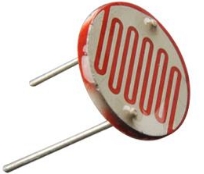
Light Dependant Resistors: An LDR is a light dependant resistor. Its resistance changes with the intensity of light. In dark condition LDRs contain few free electrons and so have a high resistance. If however light is shone onto an LDR more electrons are freed and the resistance decreases. LDRs are often used in light sensitive circuits in devices such as photographic equipment, automatic lightning controls and burglar alarms.
Thermistor: A thermistor is a temperature dependant resistor. It is made from a semiconducting material such as silicon or germanium. At room temperature the number of free electrons is small and so the resistance of a thermistor is large. If however if it is warmed the number of the electrons increases and its resistance decreases. Thermistors are often used in temperature-sensitive circuits in devices such as fire alarms and thermostats.
2.13 know that lamps and LEDs can be used to indicate the presence of a current in a circuit
A light-emitting diode (LED) is a special kind of diode that glows when electricity passes through it. Most LEDs are made from a semi-conducting material called gallium arsenide phosphide.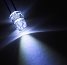
LEDs can be bought in a range of colours. They can also be bought in forms that will switch between two colours (bi-colour), three colours (tri-colour) or emit infra-red light.
In common with all diodes, the LED will only allow current to pass in one direction. The cathode is normally indicated by a flat side on the casing and the anode is normally indicated by a slightly longer leg. The current required to power an LED is usually around 20 mA.
2.14 know and use the relationship between voltage, current and resistance:
voltage = current × resistance
V = I × R
2.15 understand that current is the rate of flow of charge
The size of an electric current indicates the rate at which charge flows. Charge(Q) is measured in coulombs (C). Current is measured in amperes (A). If 1 C of charge flows along a wire every second the current passing the wire is 1A.
2.16 know and use the relationship between charge, current and time:
charge = current × time
Q = I × t
2.17 know that electric current in solid metallic conductors is a flow of negatively charged electrons
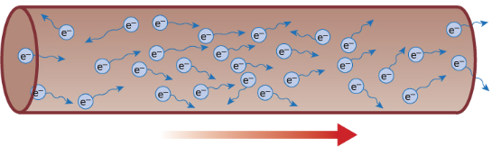
Current is the flow of charge. One coulomb of charge is equivalent of the charge carried by approximately six million, million, million (6 x 10¹⁸) negative electrons.
Charge direction when connected to a battery
In conductors some electrons are free to drift. But the number of electrons flowing in any one direction is roughly equal to the number flowing in the opposite direction. There is therefore no overall flow of charge. However, if a cell or battery is connected across the conductor, more of the electrons now flow in the direction away from the negative terminal and towards the positive terminal, than in the opposite direction. There is now a net flow of charge.
Electrons/charges move from the negative terminal to positive. But when you are dealing with topics such as circuit and motors, it is still considered that current flow from positive to negative. This is called conventional current.
2.18 understand that:
- voltage is the energy transferred per unit charge passed
- the volt is a joule per coulomb.
As the charges flow around a circuit, the energy they carry is converted into other forms of energy by the components they pass through. The voltage across each component tells us how much energy it is converting. If the voltage across a component is 1v, this means that the component is changing 1J of electrical energy into a different kind of energy each time 1C of charge passes through it.
d) Electric charge
2.19 identify common materials which are electrical conductors or insulators, including metals and plastics
Conductors: Electrical conductors are materials that allow current to pass through them. Conductors have free electron diffusion to pass current. Metals like copper, silver, aluminium havefree electrons and can conduct electricity.
Insulators: Insulators do not conduct electricity because they don’t have free electrons. Examples of insulators are plastics, rubber, wood etc.
2.20 describe experiments to investigate how insulating materials can be charged by friction
Experiment: To investigate how insulating materials can be charged by friction
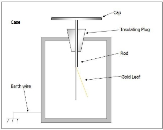
Apparatus: Glass rod, silk cloth, electroscope
Procedure:
- Take a glass rod and silk cloth.
- Rub the rod with the cloth.
- Now, take any of the two materials near the metal plate of an electroscope.
Observation
- You will notice that the leaf below will deflect.
- This will prove that charge can be produced by friction.
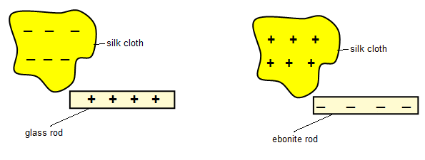
2.21 explain that positive and negative electrostatic charges are produced on materials by the loss and gain of electrons
If two materials are rubbed together electrons will be transferred. The one that gains electrons will be negatively charged and the one that losses electrons will be positively charged.
| Materials | Positive charge | Negative charge |
|---|---|---|
| Glass rod rubbed with silk | glass | Silk |
| Ebonite rod rubbed with fur | fur | ebonite |
| Perspex ruler rubbed with woolen | Perspex | Duster |
| Plastic comb rubbed with hair | hair | Plastic comb |
| Polythene strip rubbed with woolen duster | duster | Polythene |
| Cellulose acetate rubbed with woolen duster | acetate | duster |
2.22 understand that there are forces of attraction between unlike charges and forces of repulsion between like charges
Similar charges repel each other and unlike charges attract each other. The attraction and repulsion occurs because of electrostatic force.
Experiment: To investigate unlike charge attracts
Apparatus:
- Two pieces of glass rods.
- One piece of silk cloth
- Insulating thread.
Diagram:

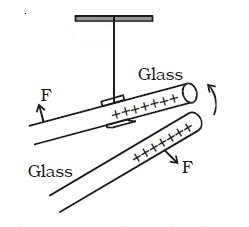
Procedure:
- Two glass rods are rubbed by silk cloth. The rods become positively charged and the cloth becomes negatively charged.
- One positive charged glass rod is hung by an insulating thread.
- Another positively charged glass rod is approached towards the hung rod.
Observation:
We will see that the hung rod move away.
Conclusion:
Like charges repels.
Experiment: To investigate that like charge repels.
Apparatus:
- One piece of glass rod
- One piece of ebonite rod
- Two pieces of silk rod
- Insulating thread.
Diagram:
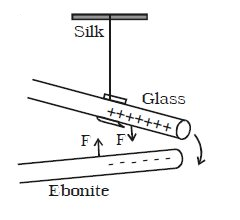
Procedure:
- Two silk clothes are taken. When the glass rod is rubbed with the silk cloth, the glass rod becomes positively charged. Again, when with another silk cloth, the ebonite rod is rubbed, it becomes negatively charged.
- The positively charged glass rod is hung by an insulating thread.
- The negatively charged ebonite rod is approached towards the hung rod.
Observation:
We will see the hung rod moves towards the glass rod.
Conclusion:
Unlike charges attract.
Experiment: Showing that a charged object can attract an uncharged object
If you charge a balloon by rubbing it against your jumper or your hair and then hold the balloon against a wall, you will find that the balloon sticks to the wall. There is an attraction between the charged balloon and the uncharged wall.

After the balloon has been charged with static electricity, but before it is brought close to the wall, the charges will be distributed. The balloon is negatively charged and the wall is uncharged – that is, the equal numbers of positive and negative charges.
As the negatively charged balloon is bought closer to the wall some of the negative electrons are repelled from the surface of the wall. This gives the surface of the wall a slight positive charge that attracts the negatively charged balloon.
2.23 explain electrostatic phenomena in terms of the movement of electrons
An electrostatic phenomenon is an event where electricity has a special effect, for example a static shock. Electrons move from one material to another. Materials with a negative charge will look for some way to earth like clouds through lightning.
2.24 explain the potential dangers of electrostatic charges, eg when fuelling aircraft and tankers
In some situations the presence of static electricity can be a disadvantage.
- As aircraft fly through the air, they can become charged with static electricity. As the charge on an aircraft increases so too does the potential difference between it and earth. With high potential differences her is the possibility of charges escaping to the earth as a spark during refueling, which could cause an explosion. The solution to this problem is to earth the plane with a conductor as soon as it lands and before refueling commences. Fuel tankers that transport fuel on roads must also be earthed before any fuels is transferred to prevent sparks causing a fire or explosion.
- Television screens and computer monitors become charged with static electricity as they are used. The charges attract light uncharged particles-that is dust.
- Our clothing can, under certain circumstances become charged with static electricity. When we remove the clothes there is the possibility of receiving a small electric shock as the charges escape to the earth.
- Workers handing electronic components must take care not to become charged by static as this can easily destroy expensive components. They wear earthing straps and work on earthed metal benches to prevent this.
2.25 explain some uses of electrostatic charges, eg in photocopiers and inkjet printers.
Electrostatic charges can be used in electrostatic paint spraying, inkjet printers, photocopiers, electrostatic precipitators etc.
Electrostatic paint spraying
Painting an awkwardly shaped object such as bicycle frame with a spray can be very time consuming and very wasteful of paint. Using Electrostatic spraying can be the process efficient.
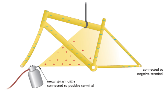
Let the metal spray nozzle be connected to a positive terminal so the paint that emerges will be positive charged. The bicycle frame should be connected to a wire and it will become negatively charged. The positively charged paint will be attracted to the frame. There is the added benefit that paint is attracted into places, such as tight corners that might otherwise not receive good coating.
Inject Printers
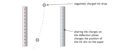
Many modern printers use inkjets to direct a fine jet of ink drops onto paper. Each spot of ink is given a charge so that as it falls between a pair of deflecting plates, electrostatic forces direct it to the correct position. The charges on the plates change hundreds of times each second so that each drop falls in a different position, forming pictures and words on the paper as required.
Photocopiers

In photocopiers, the paper is shone in bright light which reflects to a rotating drum. The dark writings and pictures do not reflect. As a result the light removes the charges in the drum. Carbon powder attaches to the charges in the drum and the pictures and writings are pasted into a sheet of paper.
Electrostatic precipitators
Many heavy industrial plants, such as steel-making furnaces and coal fired power stations, produce large quantities of smoke. This smoke carries small particles of ash and dust into the environment, causing health problems and damage to buildings. One way of removing these pollutants from the smoke is to use electrostatic precipitators.

As the smoke initially rises up the chimney, it passes through a mesh of wires that are highly charged. As they pass through the mesh, the ash and dust particles become negatively charged. Higher up the chimney these charged particles are attracted by and stick to large metal earthed plates. The cleaner smoke is then released into the atmosphere. When the earthed plates are completely covered with dust and ash, they are given a sharp rap. The dust and ash fall into collection boxes, which are later emptied.