Section 6: Magnetism and electromagnetism
(a) Units
6.1 use the following units: ampere (A), volt (V), watt (W).
Unit of current: ampere (A)
Unit of potential difference: volt (V)
Unit of power: watt (W)
(b) Magnetism
6.2 understand that magnets repel and attract other magnets and attract magnetic substances
Magnets are able to attract objects made from magnetic materials such as iron, steel, etc. Other objects like plastic, rubber are non-magnetic substance. They can’t attract magnet.
Magnets have two poles: North Pole and South Pole. North Pole and South Pole attract each other. Similar poles like North Pole and North Pole or South Pole and South Pole repel each other.
6.3 describe the properties of magnetically hard and soft materials
| Magnetically hard materials | Magnetically soft materials |
|---|---|
| Needs time to become magnetized | Easily gets magnetized |
| Once magnetized, the magnetism remains permanently | Loses its magnetism easily |
| Magnets withmagnetically hard materials are known as permanent magnets | Magnets withmagnetically soft materials are known as temporary magnets |
| Eg: Steel | Eg: Iron |
6.4 understand the term ‘magnetic field line’
Magnetic field is a volume of space where magnetism can be detected.
Magnetic fields are drawn using lines of force or flux lines. This lines are imaginary but they:
show the shape of magnetic field.
show the direction of the magnetic field – the field lines travel from north to south.
show the strength of the magnetic field – the field lines are closest together where the magntic field is strongest.
6.5 understand that magnetism is induced in some materials when they are placed in a magnetic field
If you keep a material in a magnetic field, eventually after a period of time, that material will be magnetized.
Example:
Place a magnetically soft material close to a strong magnet. The soft iron bar becomes an induced magnet with the end nearer the magnet having opposite polarity to that of the magnet.
A steel bar is placed inside a coil. After a while the bar becomes magnetized due to the magnetic induction from solenoid. The polarities of the magnet depend on the direction of current flow.
6.6 describe experiments to investigate the magnetic field pattern for a permanent bar magnet and that between two bar magnets
Experiment: To investigate the magnetic field pattern for a permanent bar magnet.
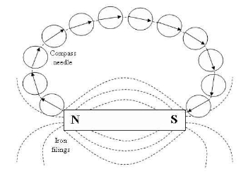
Apparatus: Bar magnet, plotting compass and a plain paper.
Procedure:
Place the bar magnet at the centre of the piece of paper so that its N-pole faces North and its S-pole faces South.
Starting near one pole of the magnet, the position ends, N and S, of the compass needle are marked by pencil dots X and Y. The compass is then moved until one end is exactly over Y and the new position of other end is marked with a third dot.
Repeat the process of marking the dots. Join the series of dots and this will give the plot of the field lines of the magnetic field.
Precautions:
Check that the plotting compass in good working order.
Ensure that there is no strong magnetic field around the plotting compass.
Experiment: To plot magnetic field using iron fillings
Apparatus: Iron fillings, Bar magnet
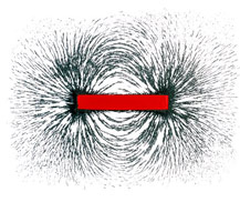
Procedure:
Place a sheet of paper over a bar magnet. Sprinkle a thin layer of Iron filings over the paper and then tap the paper gently. The iron filings act like thousands of tiny compasses and point themselves along the lines of flux.
6.7 describe how to use two permanent magnets to produce a uniform magnetic field pattern.
Apparatus: Two bar magnets

Procedure:
By keeping the opposite poles face each other. The region between the poles would establish magnetic field that would be uniform.
(c) Electromagnetism
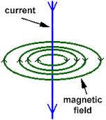
6.8 understand that an electric current in a conductor produces a magnetic field round it
When a current flows through a wire a magnetic field is created around the wire. This phenomenon is called electromagnetism. The field around the wire is quite weak and circular in shape. The direction of the magnetic field depends up the direction of the current and can be found using the right-hand grip rule.
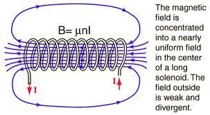
6.9 describe the construction of electromagnets
If a temporary magnet is wrapped with a wire into a coil and pass current to it, the magnet will become magnetized. This way electromagnets can be constructed.
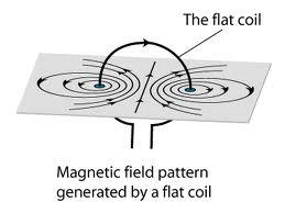
6.10 sketch and recognize magnetic field patterns for a straight wire, a flat circular coil and a solenoid when each is carrying a current
A field around a straight wire is simply a series of circles around the wire.
A field around a solenoid is similar to that of a bar magnet.
A field around a flat coil is basically like a single wire, but there are two.
6.11 understand that there is a force on a charged particle when it moves in a magnetic field as long as its motion is not parallel to the field
A charged particle has a magnetic field around it. When a charged particle moves through another magnetic field, it experiences a force. This is because of the overlapping of the two magnetic fields. However, if the charged particle is moved parallel to that field, no force will be exerted. As an electric current is a flow of electrons, we can see this effect when a wire carrying the current is put into a magnetic field too.
6.12 understand that a force is exerted on a current-carrying wire in a magnetic field, and how this effect is applied in simple d.c. electric motors and loudspeakers

If we pass a current through a piece of wire held at right angle to the magnetic field of a magnetic field of a magnet, the wire will move. The motion is the result of forces created by overlapping magnetic field around the wire and the magnet.
When a current flows along a wire a cylindrical magnetic field is created around the wire. If the wire is placed between the poles of a magnet, the two fields overlap. In certain places, the fields are in the same direction and so reinforce each other, producing a strong magnetic field. In other places, the fields are in opposite directions, producing a weaker field. The wire experiences a force, pushing it from the stronger part of the field to the weaker part. This is called the motor effect.

The moving – coil loudspeaker:

Signals from a source, such as an amplifier, are fed into the coil of the speaker as currents that are continually changing in size and direction. The overlapping fields of the coil and the magnet therefore create rapidly varying forces on the wires of the coil, which cause the speaker cone to vibrate. These vibrations create the sound waves we hear.
The electric motor:

As current passes around the loop of wire, one side of it will experience a force pushing it upwards. The other side will feel a force pushing it downwards, so the loop will rotate. Because of the split ring, when the loop is vertical, the connections to the supply through brushes swap over, so that the current flowing through each side of the loop changes direction. The wire at the bottom is now pushed upwards and the wire at the top is pushed downwards – so the loop carries on turning. The arrangement of brushes and split ring changes the direction of the current flowing through the loop every half turn, which means the rotation can be continuous.
6.13 use the left hand rule to predict the direction of the resulting force when a wire carries a current perpendicular to a magnetic field
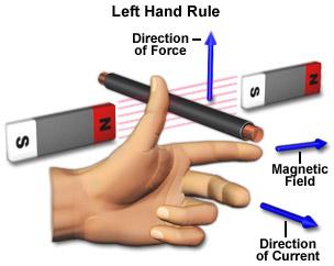
The left hand rules shows the direction of force, magnetic field and current when a wire carries a current perpendicularly to a magnetic field.
The pointing finger points the magnetic field from North to South
The middle finger points the direction of current in wire.
The thumb shows the resulting force.
6.14 describe how the force on a current-carrying conductor in a magnetic field increases with the strength of the field and with the current.
Ways to increase the force produced in motors:
- Increase the number of turns or loops of wire (to make a coil)
- Increase the strength of magnetic field
- Increase the current flowing through the loop of wire
(d) Electromagnetic induction
6.15 understand that a voltage is induced in a conductor or a coil when it moves through a magnetic field or when a magnetic field changes through it and describe the factors which affect the size of the induced voltage
When a wire cuts the magnetic field of a magnet, a voltage is induced in the wire. This phenomenon is called electromagnetic induction.

If we move a wire across a magnetic field at right angles, a voltage is induced in the wire. The size of the induced voltage can be increased by:
- moving the wire more quickly
- using a stronger magnet
- wrapping the wire into a coil so that more pieces of wire move through the magnetic field.
We can generate a voltage and current by pushing a magnet into a coil. The size of induced voltage can be increased by:
- moving the magnet more quickly
- using a stronger magnet
- using a coil with a larger cross-sectional area.

Faraday’s Law of Electromagnetic Induction:
“The size of the induced voltage across the ends of a wire (coil) is directly proportional to the rate at which the magnetic lines of flux are being cut.”
This says that:
- a voltage and current are generated when a conductor such as wire cuts through the magnetic field lines.
- the faster the lines are cut the larger the induced voltage and current.
6.16 describe the generation of electricity by the rotation of a magnet within a coil of wire and of a coil of wire within a magnetic field and describe the factors which affect the size of the induced voltage
In a generator, when the coil rotates, its wire cut through magnetic field lines and a current is induced in them. If we watch just one side of the coil, we see that the wire moves up through the field and then down for each turn of the coil. As a result, the current induced in the coil flows first in one direction and then in the opposite direction. This kind of current is called alternating current. A generator that produces alternating current is called an alternator. The size of the induced voltage can be increased by using much stronger magnets, many more turns of wire on the coil and spinning the coil much faster.

6.17 describe the structure of a transformer, and understand that a transformer changes the size of an alternating voltage by having different numbers of turns on the input and output sides
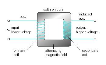
A transformer is a device that helps to reduce or increase voltage in a wire or electric line. This is made of two soft iron core linking to the coils at the two end of the transformer. The first coil is called the primary coil and the second one is called the secondary coil. When alternating current is passed through a coil, the magnetic field around it is continuously changing. The changing magnetic field will cut the secondary coil and induce voltage in it, and that’s how current is passed. If the secondary coil has more turns than the primary coil, it is a step-up transformer where output the voltage will increase. If the secondary coil has less turns than the primary, it is a step-down transformer where theoutput voltage will decrease.
Why transformer doesn’t work with direct current?
Transformers only work if the magnetic field around the primary coil is changing. Transformers will therefore only work with ac currents and voltages. They will not work with dc current and voltages.
6.18 explain the use of step-up and step-down transformers in the large- scale generation and transmission of electrical energy
After generating electricity, electric currents are passed to a step-up transformer which increase the voltage and decrease the current. This is because higher currents need wide and expensive wire to pass through. Or else, energy is lost in form of heat. Using transformers mean we can have a solution to this problem. Before the electricity reaches home, those are passed through step-down transformers to decrease the voltage and increase the current at the same time.
6.19 know and use the relationship between input (primary) and output (secondary) voltages and the turns ratio for a transformer:
input voltageoutput voltage=number of turns on primary coilnumber of turns on secondary coil
VpVs=npns
6.20 know and use the relationship: for 100% efficiency
If a transformer is 100% efficient, the electrical energy entering the primary coil is equal to the electrical energy leaving the secondary coil.
Input power = output power
VP IP= VS IS